AutoCAD is one of the most widely used computer-aided design (CAD) software tools in the field of civil engineering. It provides engineers, architects, and designers with a powerful platform to create precise drawings and models that are essential for planning, designing, and managing civil engineering projects. This comprehensive guide will walk you through how to effectively use AutoCAD for civil engineering projects, covering everything from basic concepts to advanced techniques.

Table of Contents
- Introduction to AutoCAD in Civil Engineering
- Why Use AutoCAD for Civil Engineering Projects?
- Setting Up AutoCAD for Civil Engineering
- Understanding AutoCAD Interface and Tools
- Creating and Managing Civil Engineering Drawings
- Working with Layers and Object Properties
- Using AutoCAD for Site Planning and Layout
- Designing Roads and Highways in AutoCAD
- Creating Topographic Maps and Contours
- Drainage and Stormwater Management Design
- Utility and Pipeline Design
- Structural Components and Reinforcement Detailing
- Collaboration and Sharing in AutoCAD
- Exporting and Printing Plans
- Tips and Best Practices for Civil Engineers Using AutoCAD
- Learning Resources and Further Reading
- Conclusion
1. Introduction to AutoCAD in Civil Engineering
AutoCAD is a versatile CAD software developed by Autodesk that allows users to create 2D drawings and 3D models with precision. In civil engineering, it is used extensively for designing infrastructure such as roads, bridges, buildings, pipelines, and land development projects. The software helps translate design concepts into technical drawings that can be shared with construction teams, project managers, and regulatory authorities.

Civil engineers rely on AutoCAD to ensure accuracy, efficiency, and compliance with design standards. The ability to visualize projects digitally before actual construction reduces errors and helps optimize resource use.
2. Why Use AutoCAD for Civil Engineering Projects?
AutoCAD offers several advantages for civil engineering projects:
- Precision and Accuracy: AutoCAD’s coordinate-based drawing system enables millimeter-level precision, which is critical for engineering designs.
- Standardization: Supports industry standards for symbols, annotations, and dimensioning which ensures consistency.
- Versatility: Can handle a wide range of civil engineering tasks from site layout to structural detailing.
- Time Efficiency: Automates repetitive tasks through commands, scripts, and templates.
- Integration: Supports importing and exporting of data from other software like GIS, Revit, and Civil 3D.
- Visualization: Provides 3D modeling capabilities for better visualization of terrain and structures.
- Documentation: Facilitates the creation of detailed documentation and construction drawings.
- Collaboration: Enables easier sharing and collaboration via DWG files and cloud services.
3. Setting Up AutoCAD for Civil Engineering
Before starting a civil engineering project in AutoCAD, it is essential to configure the software for your specific needs.
a. Choose the Right AutoCAD Version
For civil engineering, consider using AutoCAD Civil 3D, which is specialized for civil design and includes tools for terrain modeling, corridor design, and pipe networks. However, standard AutoCAD can also be used effectively for many tasks.
b. Template Setup
Create or download templates that include:
- Drawing units set to meters or feet depending on the project location.
- Predefined layers with standardized names (e.g., roads, utilities, contours).
- Title blocks and border layouts ready for printing.
- Dimension styles and text styles matching your project standards.
c. Customize Tool Palettes and Workspaces
Organize frequently used commands and tools on custom tool palettes and save your workspace layout for easy access.
4. Understanding AutoCAD Interface and Tools
A solid understanding of AutoCAD’s interface is necessary for efficient workflow.
a. Key Interface Components
- Ribbon: Contains tabs and panels with grouped commands.
- Command Line: Where you enter commands and view prompts.
- Drawing Area: The space where you create your design.
- Status Bar: Displays drawing aids such as grid, snap, and ortho mode.
- Navigation Tools: Pan, zoom, and orbit controls.
b. Essential Tools for Civil Engineering
- Line, Polyline, and Spline: Basic drawing tools for creating shapes and paths.
- Offset and Fillet: For creating parallel lines or rounded corners.
- Trim and Extend: Editing tools to modify existing geometry.
- Dimensioning: Tools for linear, angular, radial, and ordinate dimensions.
- Hatch: For filling areas with patterns indicating materials or zones.
- Blocks: Reusable symbols like manholes, trees, or road signs.
- Layers: For organizing different types of objects on separate layers.
- External References (Xrefs): Inserting drawings into other drawings to maintain coordination.
5. Creating and Managing Civil Engineering Drawings
a. Starting a New Project
Begin by setting up your drawing environment with correct units and scale. Import any necessary base files such as survey data, GIS maps, or previous designs.
b. Drawing Precision
Use object snaps (osnap) like endpoint, midpoint, center, intersection to ensure accurate connections. Employ grid and snap settings to maintain alignment.
c. Using Coordinates
Civil engineering projects often rely on real-world coordinates. Use absolute and relative coordinate input to create precise layouts.
6. Working with Layers and Object Properties
Proper layer management is crucial in civil engineering drawings to keep elements organized.
a. Creating Layers
Create layers for specific elements such as:
- Roads (e.g., Layer: RD_Main)
- Utilities (e.g., Layer: UTIL_Water)
- Contours (e.g., Layer: TOPO_Contour)
- Structural elements (e.g., Layer: STR_Foundation)
b. Layer Properties
Assign colors, linetypes, and lineweights to layers to visually differentiate elements.
c. Using Filters and Layer States
Filter layers to isolate specific project elements and save layer states for different views.
7. Using AutoCAD for Site Planning and Layout
a. Importing Survey Data
Civil engineers often start with survey data. Import points, polylines, and contours from survey files (CSV, TXT, or LandXML).
b. Creating Site Boundaries
Use polylines to define property boundaries, easements, and right-of-way lines.
c. Plotting Utilities and Access Roads
Draw roads, parking lots, sidewalks, and utility layouts using polylines and blocks.
8. Designing Roads and Highways in AutoCAD
a. Road Alignment
Define horizontal and vertical alignments using polylines and splines.
b. Cross Sections and Profiles
Draw cross-sectional views of roads showing pavement layers, shoulders, slopes, and ditches.
c. Using AutoCAD Civil 3D
Civil 3D offers specialized tools for corridor modeling, earthwork calculations, and superelevation design.
9. Creating Topographic Maps and Contours
a. Contour Lines
Use elevation data to create contour lines representing terrain.
b. Surface Modeling
Generate 3D surfaces from points and breaklines to visualize topography.
c. Volume Calculations
Calculate cut and fill volumes for earthworks.
10. Drainage and Stormwater Management Design
a. Designing Drainage Networks
Draw pipe networks, inlets, manholes, and channels.
b. Hydraulic Calculations Integration
Use Civil 3D or integrate with external hydrology software to size pipes and retention basins.
c. Annotating Flow Directions
Use arrows and labels to indicate flow paths.
11. Utility and Pipeline Design
a. Layout of Water, Sewer, Gas Lines
Draw pipelines with appropriate symbols and line types.
b. Manhole and Valve Placement
Use blocks for standardized components.
c. Clash Detection
Check for conflicts between utilities using layering and 3D visualization.
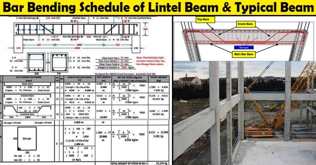
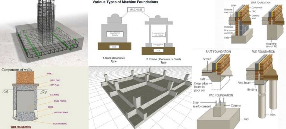
12. Structural Components and Reinforcement Detailing
a. Foundations and Retaining Walls
Draw plans and sections with dimensions and notes.
b. Rebar Detailing
Use blocks and hatch patterns to indicate reinforcement.
c. Integration with Structural Software
Export drawings to structural analysis software or import structural models.
13. Collaboration and Sharing in AutoCAD
a. Using External References (Xrefs)
Link drawings for modular project management.
b. Cloud Storage and Autodesk BIM 360
Share files and collaborate in real-time.
c. Exporting Formats
Export to PDF, DWF, or DWG for sharing with stakeholders.
14. Exporting and Printing Plans
a. Setting Up Layouts
Create paper space layouts with title blocks and viewports.
b. Plot Styles
Apply color-to-black or lineweight plot styles as required.
c. Printing and Publishing
Print plans in appropriate scale and format.
15. Tips and Best Practices for Civil Engineers Using AutoCAD
- Always use layers systematically.
- Keep your drawings clean and avoid unnecessary objects.
- Use blocks for repetitive symbols.
- Regularly save and backup your work.
- Use keyboard shortcuts to speed up work.
- Verify units and scales before starting.
- Use annotation scaling for consistent text and dimension sizes.
- Attend AutoCAD training or tutorials to improve skills.
- Keep software updated for best performance and new features.
16. Learning Resources and Further Reading
- Autodesk Official Training Guides
- Online Courses on platforms like Udemy, Coursera
- YouTube Channels dedicated to AutoCAD tutorials
- Civil 3