The manual design of beams and columns is a fundamental process in structural engineering, involving calculations based on material properties, design loads, and building code specifications (e.g., ACI, Eurocode, IS). The general procedure for both reinforced concrete and steel members follows a similar set of sequential steps.
🛠️ General Manual Design Steps
- Preliminary Sizing: Estimate the initial dimensions (width, depth/height) of the beam or column based on span length or storey height, and architectural constraints. This provides a starting point for load calculation.
- Determine Design Loads: Calculate all loads that the member must support. This includes:
- Dead Load (DL): Permanent loads like the self-weight of the member, slab, walls, and fixed equipment.
- Live Load (LL): Variable loads from occupants, furniture, or vehicles.
- Environmental Loads: Wind, seismic, and snow loads (where applicable).
- Apply Load Combinations: Apply partial factors of safety to the characteristic loads and combine them according to the relevant building code to determine the maximum design ultimate load ($W_u$) for strength checks (e.g., $1.2 \cdot DL + 1.6 \cdot LL$).
- Structural Analysis: Analyze the structure to determine the internal design forces—maximum bending moment ($M_{max}$), shear force ($V_{max}$), and axial force ($N$)—using methods like the force method, slope-deflection, or moment distribution, or by using codified coefficients for standard cases.
- Design and Verification: Use the internal design forces to calculate the required member size or reinforcement area, and then check against all code-specified limit states.
🏗️ Reinforced Concrete (RC) Beams and Columns
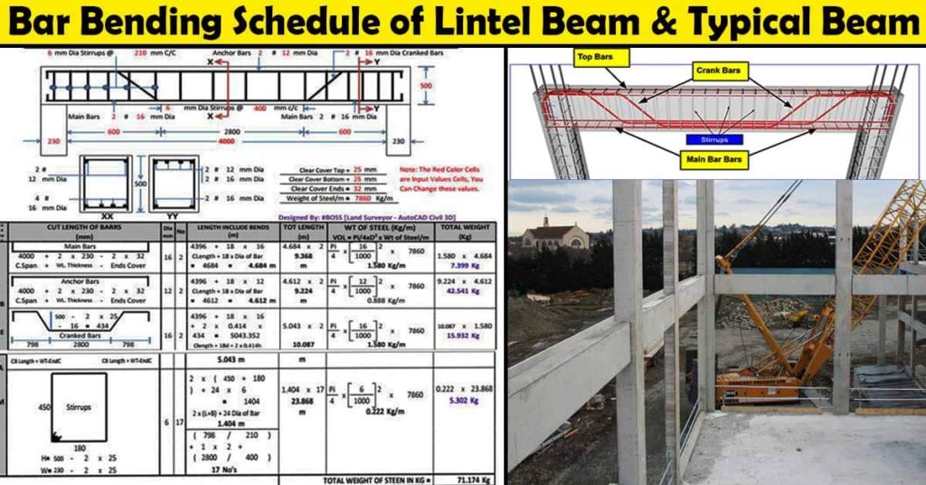
1. RC Beam Design (Focus on Flexure and Shear)
The design aims to resist the bending moment (Flexure) and shear force.
- Flexural Design:
- Calculate the required area of longitudinal tension steel ($A_s$) to resist the maximum bending moment ($M_{max}$).
- Check if the concrete section size is adequate (e.g., check for a singly vs. doubly reinforced section).
- Determine the size and number of reinforcing bars to provide the required $A_s$.
- Shear Design:
- Check the maximum shear stress ($v$) against the allowable shear stress capacity of the concrete section ($v_c$) to determine if shear reinforcement (stirrups/links) is required.
- If needed, calculate the required spacing and diameter of the stirrups to resist the excess shear force.
- Serviceability Checks:
- Check Deflection by comparing the actual span-to-effective-depth ratio ($L/d$) to the allowable limit, often with modification factors.
- Check Cracking (if required by the code) by limiting bar spacing or diameter.
- Detailing: Ensure proper anchorage and curtailment of the reinforcement bars.
2. RC Column Design (Focus on Axial Load and Bending)
The design is governed by the axial force ($N$) and any accompanying bending moments ($M_x, M_y$).
- Slenderness Check: Determine if the column is short or slender. Slender columns require additional checks for secondary moments (P-Delta effects).
- Short Column Design:
- For an axially loaded short column, calculate the required area of longitudinal steel ($A_{sc}$) based on the maximum axial load.
- For a column with uniaxial or biaxial bending (axial load + moment), use Interaction Diagrams or design charts to find the required cross-section and steel area that can safely carry the combined $N$ and $M$.
- Reinforcement Detailing:
- Verify the minimum and maximum percentages of steel.
- Determine the diameter and spacing of the lateral ties/links (shear/confinement reinforcement).
⚙️ Steel Beam and Column Design
Steel design, typically using steel manuals (like AISC), involves selecting an appropriate rolled section (e.g., I-beam, W-shape) that satisfies strength and stability requirements.
1. Steel Beam Design
- Select Tentative Section: Choose a preliminary steel shape based on the required section modulus ($S_{req} = M_{max} / F_y$) or using load tables from a steel design manual.
- Strength Checks (Limit States): Verify the capacity of the selected section against several limit states:
- Bending (Flexure): Check yielding, lateral-torsional buckling, and local buckling.
- Shear: Verify that the shear force ($V_{max}$) is less than the shear strength of the web.
- Serviceability Check: Verify Deflection by calculating the actual maximum deflection ($\Delta_{act}$) under service loads and comparing it to the allowable limit (e.g., $L/240$).
2. Steel Column Design
- Determine Effective Length: Find the column’s effective length ($KL$) based on its end-support conditions (fixed, pinned, etc.) and whether the frame is braced or unbraced, using charts like the alignment charts.
- Compression Check: Calculate the slenderness ratio ($KL/r$) and use it to determine the column’s nominal compressive strength ($P_n$) to ensure the axial load ($N$) is safely carried.
- Combined Loads (Beam-Column): If the column is subjected to both axial load and moment, use an interaction equation (e.g., $N/P_n + M/M_n \leq 1.0$) to verify that the member can safely carry the combination of forces.
The video below demonstrates the manual hand calculation steps for designing a simple steel beam.
How To Design a Steel Beam For Beginners: Hand Calculation & Software is relevant as it provides a practical walkthrough of the manual calculation and verification steps for steel beam design.