Accurately calculating earthwork is a foundational skill in construction and civil engineering. It’s the process of determining the exact volume of soil and rock that needs to be excavated (cut) or added (fill) to bring a project site to the desired design grade. Getting this calculation right is critical for project budgeting, bidding, scheduling, and logistics. Underestimate, and you face costly change orders and delays. Overestimate, and your bid becomes uncompetitive.
This guide will walk you through the entire process, from understanding the core concepts to applying different calculation methods, and accounting for the practical factors that separate a theoretical calculation from a realistic estimate.
Chapter 1: The Core Concepts: Cut, Fill, and Balance
Before diving into calculations, it’s essential to understand the key terms and the overarching goal.
- Cut: The volume of soil/rock that needs to be removed from the existing ground to reach the design elevation.
- Fill: The volume of soil/rock that needs to be added to the existing ground to raise it to the design elevation.
- Design Grade (or Finished Grade): The final, intended elevation and slope of the land after construction, as specified in the project plans.
- Existing Grade (or Natural Grade): The current, pre-construction elevation and slope of the land.
- Subgrade: The level to which the ground must be excavated to place the foundation for a structure, road, or slab. This is below the final finish grade.
- Borrow: The site where excess soil is taken to. If you have more fill than cut, you need to “borrow” soil from another location.
- Waste: The site where excess soil is disposed of. If you have more cut than fill, you need to “waste” or haul away the surplus soil.
- Balance Point: The ideal scenario where the total volume of cut exactly equals the total volume of fill, minimizing the need for importing or exporting soil.
The Primary Goal of Earthwork Calculation: To determine the net difference between cut and fill volumes, allowing project managers to plan for equipment, hauling trucks, and material sourcing, thereby controlling costs and timelines.
Chapter 2: The Prerequisites: What You Need to Start
You cannot calculate earthwork in a vacuum. You need specific data to begin.
- Existing Topographic Survey: This is a detailed map of the current site conditions, showing the existing elevations (contour lines) and key features. This is your “before” picture. The accuracy of your calculation is directly tied to the accuracy and density of this survey data.
- Design Grading Plan: This is the engineering drawing that shows the final, intended elevations and slopes of the site after construction. This is your “after” picture. It will include contour lines, spot elevations, and slopes.
- Soil Report (Geotechnical Investigation): As detailed in the previous article on soil testing, this report is crucial. It tells you the soil type, its properties, and, most importantly, the Swell and Shrinkage Factors (explained in detail in Chapter 5).
Chapter 3: The Calculation Methods
There are several methods for calculating earthwork volumes, ranging from simple and approximate to highly complex and precise. The choice of method depends on the project’s size, complexity, and required accuracy.

Method 1: The Cross-Section Method
This is one of the most common and versatile methods, widely used for linear projects like roads, railways, canals, and pipelines.
The Process:
- Establish Cross-Sections: Draw a series of perpendicular lines (cross-sections) across the project alignment at regular intervals (e.g., every 50 feet) or at points where the ground slope changes significantly.
- Plot Existing and Design Grades: On each cross-section, plot both the existing ground profile (from the survey) and the proposed design profile (from the grading plan).
- Calculate Cross-Sectional Areas: For each cross-section, calculate the area of the “cut” profile and the area of the “fill” profile. This can be done using:
- Planimeter: A physical or digital tool for measuring area.
- Coordinate Geometry: Using the coordinates of the points that make up the cut and fill shapes.
- CAD Software: The most common method today; software can automatically calculate the hatched area.
- Compute Volume Between Sections: The volume between two adjacent cross-sections is calculated using the Average End Area Method. Formula: Volume = L * (A₁ + A₂) / 2 Where:
V= Volume (Cu. Yd. or Cu. M)L= Distance between the two cross-sections (Ft. or M)A₁= Area of Cut (or Fill) at the first station (Sq. Ft. or Sq. M)A₂= Area of Cut (or Fill) at the next station (Sq. Ft. or Sq. M)
Example:
Calculating cut volume between two sections for a road:
- Distance between sections,
L= 50 ft - Cut Area at Station 1+00,
A₁= 150 Sq. Ft. - Cut Area at Station 1+50,
A₂= 100 Sq. Ft. - Volume (Cu. Ft) = 50 * (150 + 100) / 2 = 50 * 125 = 6,250 Cu. Ft.
- Volume (Cu. Yd) = 6,250 / 27 ≈ 231.5 Cu. Yd.
This process is repeated for every pair of cross-sections for both cut and fill, and the results are summed up in a table to get the total volumes.
Method 2: The Grid Method (or Borrow-Pit Method)
This method is best suited for large, relatively flat sites like parking lots, industrial yards, and building pads. It involves overlaying a grid onto the site and calculating the cut/fill at each grid point.
The Process:
- Establish a Grid: Overlay a grid of squares (e.g., 50ft x 50ft) on the site plan. The smaller the grid, the more accurate the result.
- Determine Existing and Design Elevations: At each grid intersection (node), determine both the existing ground elevation (from the survey) and the proposed design elevation (from the grading plan).
- Calculate Cut/Fill Depth at Each Node: For each node, subtract the elevations to find the depth of cut or fill.
- Cut Depth: Existing Elevation – Design Elevation (a positive number)
- Fill Depth: Design Elevation – Existing Elevation (a positive number)
- Calculate Volume for Each Grid Cell: For each square in the grid, the volume is calculated by averaging the cut/fill depths at its four corners and multiplying by the area of the cell. Formula for One Grid Cell: Volume = A * (h₁ + h₂ + h₃ + h₄) / 4 Where:
V= Volume of the cell (Cu. Ft.)A= Area of the grid cell (Sq. Ft.)h₁, h₂, h₃, h₄= Cut/Fill depths at the four corners of the cell (Ft.)
- Sum the Volumes: Add the volumes of all individual grid cells to get the total cut and total fill for the site.
Method 3: The Contour Method
This method is less common for precise calculations but is useful for preliminary estimates or for large, undeveloped sites. It involves measuring the area enclosed by existing and proposed contour lines.
The Process:
- Overlay Contours: On a plan, you will see the existing contour lines and the proposed contour lines from the grading plan. Where they intersect, they create a series of enclosed areas.
- Measure Areas: Use a planimeter or CAD software to measure the area between successive pairs of contour lines (e.g., the area between the existing 102-ft contour and the proposed 102-ft contour).
- Calculate Volume: The volume between two contours is calculated using the average end area method, where the “areas” are the areas enclosed by the contours, and the “distance” is the contour interval.
Method 4: The Software Method (The Modern Standard)
Today, nearly all professional earthwork calculations are performed using specialized software like AutoCAD Civil 3D, Bentley GeoPak, Agtek, or Trimble Business Center.
The Process:
- Import Data: The existing surface is created by importing the topographic survey points and breaklines. The proposed surface is created from the design grading plan.
- Generate Digital Terrain Models (DTMs): The software creates a “Triangulated Irregular Network” (TIN) for both the existing and proposed surfaces. This is a highly accurate digital model of the ground.
- Volume Calculation: The software compares the two DTMs, calculating the cut and fill volume at every triangle in the TIN model. It provides a highly accurate report of total cut, total fill, and net volume.
- Visualization: These programs can generate powerful visualizations, such as cut/fill color maps, to instantly see where soil needs to be removed (cut, often in red) and where it needs to be added (fill, often in blue).
Advantage: This method is extremely fast, highly accurate, and allows for easy “what-if” scenarios. If the design changes, the volumes can be recalculated in seconds.
Chapter 4: A Step-by-Step Walkthrough (Cross-Section Method)
Let’s apply the Cross-Section Method to a simple project: leveling a building pad.
Project: Create a 100ft x 100ft level pad at an elevation of 95.0 ft.
Step 1: Gather Data
- Existing Survey: The natural ground slopes from approx. 97.0 ft on the west side to 93.0 ft on the east side.
- Design Plan: The pad is 100ft x 100ft at a constant 95.0 ft.
Step 2: Establish Cross-Sections
We’ll take three cross-sections, 50 feet apart.
- Section A-A’ (West Edge): Existing grade ~96.8 ft to ~96.2 ft.
- Section B-B’ (Center): Existing grade ~95.5 ft to ~94.5 ft.
- Section C-C’ (East Edge): Existing grade ~94.2 ft to ~93.4 ft.
Step 3: Calculate Cross-Sectional Areas (Simplified)
For each section, we calculate the area of cut and fill. Let’s assume we used CAD and found:
- Section A-A’:
- Cut Area (A₁,cut) = 15 Sq. Ft.
- Fill Area (A₁,fill) = 0 Sq. Ft.
- Section B-B’:
- Cut Area (A₂,cut) = 5 Sq. Ft.
- Fill Area (A₂,fill) = 5 Sq. Ft.
- Section C-C’:
- Cut Area (A₃,cut) = 0 Sq. Ft.
- Fill Area (A₃,fill) = 18 Sq. Ft.
Step 4: Compute Volumes Between Sections
Using L = 50 ft.
- Volume between A-A’ and B-B’:
- Cut Vol = 50 * (15 + 5) / 2 = 500 Cu. Ft. / 27 = 18.52 Cu. Yd.
- Fill Vol = 50 * (0 + 5) / 2 = 125 Cu. Ft. / 27 = 4.63 Cu. Yd.
- Volume between B-B’ and C-C’:
- Cut Vol = 50 * (5 + 0) / 2 = 125 Cu. Ft. / 27 = 4.63 Cu. Yd.
- Fill Vol = 50 * (5 + 18) / 2 = 575 Cu. Ft. / 27 = 21.30 Cu. Yd.
Step 5: Sum Total Volumes
- Total Cut Volume: 18.52 + 4.63 = 23.15 Cu. Yd.
- Total Fill Volume: 4.63 + 21.30 = 25.93 Cu. Yd.
- Net Volume: Cut – Fill = 23.15 – 25.93 = -2.78 Cu. Yd.
Conclusion: We have a slight balance toward fill. We will need to import approximately 2.78 cubic yards of fill material to complete the pad. (Note: This is before considering swell/shrinkage).
Chapter 5: The Critical Adjustment: Swell and Shrinkage
A cardinal sin in earthwork estimating is to confuse “volume in the ground” with “volume in a truck” or “volume after compaction.”
- Bank Cubic Yard (BCY): The volume of material in its natural, undisturbed state in the ground. This is the unit you calculate using the methods above.
- Loose Cubic Yard (LCY): The volume of that same material after it has been excavated and broken up. It will occupy more space due to the introduction of air voids. This is the volume in a haul truck.
- Compacted Cubic Yard (CCY): The volume of the material after it has been placed and compacted as fill. It will occupy less space than its natural state due to the removal of air voids.
The conversion between these states is governed by Swell and Shrinkage Factors.
- Swell Factor: The percentage of increase in volume when material is excavated.
- Formula: LCY = BCY × (1 + Swell%)
- Example: Common soil has a swell of 25%. 100 BCY excavated becomes 125 LCY in the trucks.
- Shrinkage Factor: The percentage of decrease in volume when material is compacted.
- Formula: CCY = BCY × (1 – Shrinkage%)
- Example: The same soil may have a shrinkage of 15%. To get 100 CCY of compacted fill, you need 100 / (1 – 0.15) ≈ 117.6 BCY of import material.
Applying this to our Walkthrough:
Let’s say our soil report gives a Swell of 20% and a Shrinkage of 10%.
- We need 25.93 CCY of Fill. How much bank material must we import?
BCY needed for Fill= CCY / (1 – Shrinkage) = 25.93 / (1 – 0.10) = 25.93 / 0.9 = 28.81 BCY
- We have 23.15 BCY of Cut. When we excavate it, how much loose volume will we have to haul away?
LCY of Waste= BCY × (1 + Swell) = 23.15 × (1 + 0.20) = 23.15 × 1.20 = 27.78 LCY
- Revised Net Balance:
- We need 28.81 BCY of fill.
- We have 23.15 BCY of cut.
- Net Import Required = 28.81 – 23.15 = 5.66 BCY.
This is a drastically different and more accurate result than our initial -2.78 Cu. Yd. Failing to account for shrinkage would have left us short of fill material.
Chapter 6: Advanced Considerations & Best Practices
- Topsoil Stripping: Often, the top layer of organic topsoil is stripped and stockpiled separately for later use in landscaping. This volume must be calculated and tracked independently.
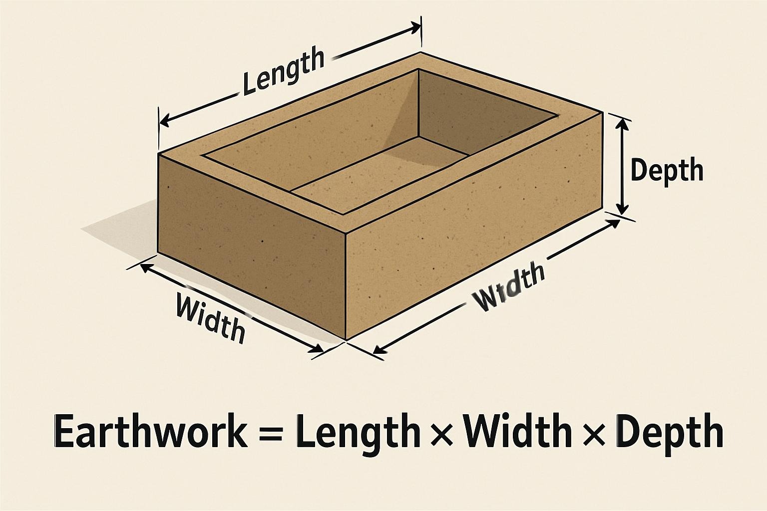
- Trench Excavation: For utilities, volume is typically calculated as:
Trench Volume = Trench Length × Width × Depth. Remember that the working space (the space needed for shoring and workers) adds to the volume. - Slope Staking: During construction, slopes must be cut accurately to prevent failure. The calculated volumes depend on these slopes being built correctly.
- Site Visits and Reality Checks: Always walk the site. The survey might not show a large pile of rubble in the corner. The best calculations can be undone by unknown site conditions.
- Contingency: Always add a contingency to your final estimate (e.g., 5-10%) to account for inaccuracies in the original survey, unexpected soil conditions, and calculation rounding.
Conclusion
Calculating earthwork is a blend of science, geometry, and practical construction knowledge. While software has automated the complex math, the fundamental principles remain vital. Understanding the difference between BCY, LCY, and CCY, and diligently applying swell and shrinkage factors, is what separates a rough guess from a reliable estimate.
By following a systematic process—gathering accurate data, choosing the right calculation method, and adjusting for real-world material behavior—you can confidently plan your excavation projects, control costs, and ensure the ground beneath your project is built on a foundation of financial and engineering certainty.