Building blueprints are essential documents in architecture, construction, and engineering, serving as the roadmap for constructing buildings and other structures. Whether you’re a homeowner planning a renovation, a student studying architecture, a contractor, or simply curious about how buildings come together, understanding how to read and interpret blueprints is a valuable skill. This comprehensive guide will take you through everything you need to know about building blueprints—from the basics and common symbols to advanced tips on reading complex plans.
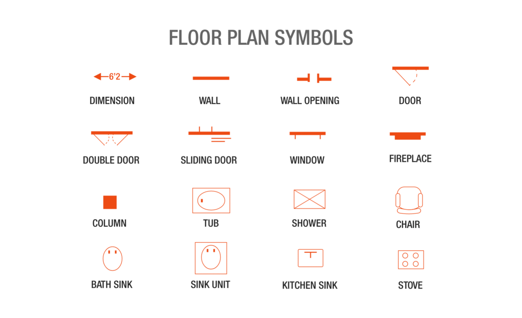
Table of Contents
- Introduction to Building Blueprints
- Types of Building Blueprints
- Understanding Scale and Dimensions
- Common Symbols and Conventions
- How to Read Floor Plans
- Elevations and Sections Explained
- Reading Electrical and Plumbing Blueprints
- Tips for Navigating Complex Blueprints
- Practical Exercises to Improve Blueprint Literacy
- Conclusion
1. Introduction to Building Blueprints
Blueprints have been used for over a century as the visual representation of architectural designs and engineering plans. Originally, blueprints were created using a contact print process on light-sensitive sheets, which produced white lines on a blue background—hence the name. Today, blueprints are typically printed on white paper with black or colored lines, but the term “blueprint” remains.
The purpose of a blueprint is to provide detailed instructions for builders and contractors to successfully construct the intended design. They show everything from spatial layouts to structural details, material specifications, and installation instructions.
2. Types of Building Blueprints
Building projects usually involve multiple types of blueprints, each focusing on a specific aspect of the construction:
- Architectural Blueprints: Show the overall design, including floor plans, elevations, sections, and details of the building’s appearance and layout.
- Structural Blueprints: Detail the framework and structural components such as beams, columns, foundation, and load-bearing walls.
- Electrical Blueprints: Indicate wiring, outlets, lighting fixtures, switches, and electrical panels.
- Mechanical Blueprints: Cover heating, ventilation, and air conditioning (HVAC) systems.
- Plumbing Blueprints: Show water supply lines, drainage, fixtures, and pipe routing.
- Site Plans: Display the location of the building on the property, including landscaping, driveways, and utility connections.
Each blueprint type uses specific symbols and conventions, so understanding the context is crucial.
3. Understanding Scale and Dimensions
Blueprints are drawn to scale, meaning that every measurement on the blueprint corresponds proportionally to real-life dimensions. Common scales include:
- 1/4 inch = 1 foot (1:48): Often used for floor plans.
- 1/8 inch = 1 foot (1:96): Used for larger projects or site plans.
- Full scale (1:1): For details or components.
How to interpret scale:
- Look for the scale notation on the blueprint, usually found in the title block or near the drawing.
- Use a scale ruler or calculator to convert measurements on the blueprint to real-world dimensions.
- Dimensions may be noted directly on the drawing, often in feet and inches, or metric units.
4. Common Symbols and Conventions
Blueprints use standardized symbols to represent various building elements. Learning these symbols is essential for accurate interpretation.
Walls
- Solid lines: Represent structural or load-bearing walls.
- Dashed lines: Indicate non-load-bearing or existing walls to be demolished.
- Double lines: Often represent exterior walls.
Doors and Windows
- Doors: Shown as a thin line with an arc indicating the swing direction.
- Windows: Represented by breaks in walls, often with thin lines or boxes.
Stairs
- Lines with arrows show stair direction and number of risers.
Electrical Symbols
- Circles, squares, or triangles represent outlets, switches, and fixtures.
- Lines indicate wiring paths.
Plumbing Symbols
- Circles with letters indicate fixtures such as sinks, toilets, bathtubs.
- Lines show water supply or drainage pipes.
Tip: Refer to the blueprint’s legend or key, usually located on the first page, which explains symbols specific to that set.
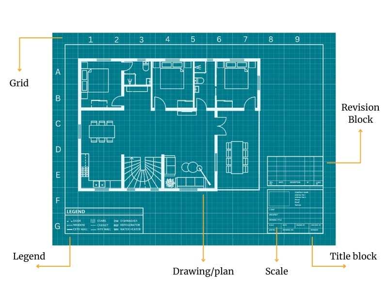
5. How to Read Floor Plans
Floor plans are the most common type of blueprint and show a horizontal section view of the building, as if you’re looking down from above.
Key Elements in Floor Plans:
- Rooms: Labeled with their function (e.g., Kitchen, Bedroom).
- Walls: Thickness and type (load-bearing vs. partition).
- Doors and Windows: Location and type.
- Fixtures: Kitchen counters, bathroom fixtures, built-in cabinets.
- Dimensions: Room sizes and wall lengths.
Steps to Read a Floor Plan:
- Identify the orientation: Look for a north arrow or site orientation.
- Locate the main entrance: This helps understand flow and layout.
- Note room labels: Understand what each space is intended for.
- Look at dimensions: Check sizes to visualize real space.
- Examine wall types: Determine which walls are structural.
- Identify fixtures: Locate kitchen appliances, plumbing fixtures.
- Check circulation paths: Study how people move through the space.
6. Elevations and Sections Explained
Elevations
Elevations are drawings of the building’s exterior walls viewed from the outside. They show:
- Wall heights
- Exterior finishes (brick, siding, stucco)
- Window and door placements
- Roof slopes and materials
- Architectural details (trim, cornices)
Sections
Sections are vertical cuts through the building, showing interior details from foundation to roof. They reveal:
- Floor-to-ceiling heights
- Structural components (beams, joists)
- Insulation and wall layers
- Staircase details
- Roof construction
By studying elevations and sections, you gain a three-dimensional understanding of the building’s form and structure.
7. Reading Electrical and Plumbing Blueprints
Electrical Blueprints
These blueprints depict the electrical wiring and fixtures. Important aspects include:
- Circuitry: Pathways of electrical wiring connecting outlets, switches, lights.
- Panel locations: Main breaker and subpanels.
- Fixture types: Types of lights, outlets, and switches.
- Special systems: Smoke detectors, security, data cabling.
Look for a legend explaining symbols such as:
- Circle with a letter for outlets.
- Switch symbol with a line to light fixtures.
- Dashed lines indicating wiring routes.
Plumbing Blueprints
Plumbing plans show water supply and drainage systems. Key elements:
- Pipes: Cold water, hot water, and waste lines.
- Fixtures: Toilets, sinks, showers, bathtubs.
- Drainage slopes: Indicated by arrows or notes to ensure proper flow.
- Cleanouts and vents: For maintenance and ventilation.
Symbols might include:
- Circles with letters (e.g., “W” for water line).
- Lines with different thickness or patterns for various pipe types.
8. Tips for Navigating Complex Blueprints
- Start with the title block: Contains project info, scale, date, and drawing number.
- Use the legend/key: Always refer to the symbol guide.
- Work from general to specific: Begin with site plans, then floor plans, then details.
- Cross-reference drawings: Compare architectural, structural, and MEP (mechanical, electrical, plumbing) plans.
- Highlight or annotate: Mark important details for quick reference.
- Ask questions: Consult with architects or engineers if unclear.
9. Practical Exercises to Improve Blueprint Literacy
- Practice with sample blueprints: Many architectural firms and educational resources provide sample drawings.
- Draw your own floor plan: Start with your home or room.
- Identify symbols: Create flashcards for common blueprint symbols.
- Visit construction sites: Compare plans to actual structures.
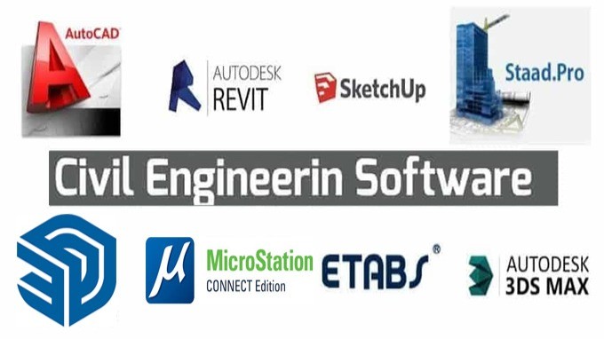
- Use software: Programs like AutoCAD or SketchUp offer digital blueprints for hands-on practice.
10. Conclusion
Reading and understanding building blueprints is a skill that unlocks insight into how structures are designed and built. By familiarizing yourself with blueprint types, scales, symbols, and drawing conventions, you can confidently interpret plans and communicate effectively with professionals in construction and design fields. Whether you’re managing a building project or simply curious about architecture, mastering blueprint literacy is a practical and rewarding endeavor.
Additional Resources
- American Institute of Architects (AIA) – Blueprint standards and guides
- National CAD Standard (NCS) – Standardized symbols and conventions
- “Architectural Graphics” by Francis D.K. Ching – A classic textbook on architectural drawing
- Online courses on platforms like Coursera, Udemy for blueprint reading
Thank you for reading! Feel free to leave questions or comments below, and happy blueprint reading!